
Project Overview
The purpose of this project was to help us better understand NAND/NOR gates as well as common cathode descriptions by building a circuit that requires them. The project had a few restraints, one of them being only 2-input gates, another one being that we were required to use at least one NAND or NOR gate. We were also required to use k-mapping to simplify our expression but I like that better anyways. This report will explain how I use inputs (a-g) to form the output (my date of birth) which is 09-04-00
Truth Table
The purpose of the truth table is to record down what segments of the seven segment display need to be on or off in order for it to display my date of birth (09-04-00}. It will also show how I need to set up my k-maps so that I can create my simplified circuit later on.

In this truth table, we have a-g columns to represent each segment in the seven segment display. Since the goal is to create your date of birth, we had to make it so that when you toggle x, y and z, then the seven segment display should show the number you are trying to show. For example, in the second row I had to make a 9 since that is the second number in my date of birth, which means that a, b, c, f and g should be on (1) and d and e should be off (0), this means that when I turn switches x and y off and z on it should display a 9. The x's at the bottom mean that we don't care what the output of those are since they are not needed, they are not needed because we only have 6 numbers to display instead of 8, therefore the bottom 2 rows are not needed.
K-mapping
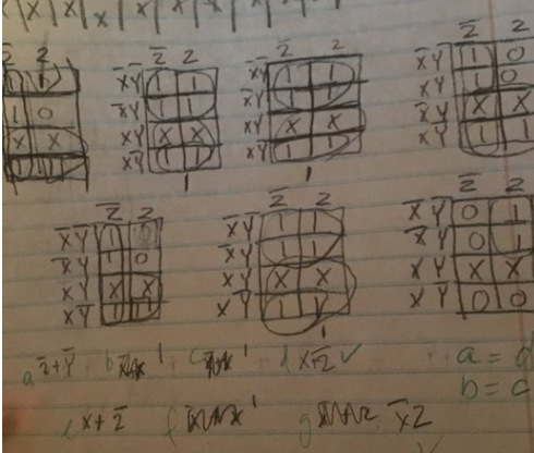
K-mapping is a process used to simplify an expression. In order to do it, you must first create the truth table and then fill in the numbers based on the truth table, however when you fill in the k-maps you must make sure that you switch the last 2 rows. Then when you have the numbers recorded you must label them and then group them in the largest area rectangle that you can, when grouping them the goal is to create the least amount of rectangles while still grouping all the ones.Fuckers in school telling me, always in the barber shop Chief Keef ain't bout this, Chief Keef ain't bout that My boy a BD on fucking Lamron and them He, he they say that nigga don't be putting in no work SHUT THE FUCK UP! Y'all niggas ain't know shit All ya motherfuckers talk about Chief Keef ain't no hitta Chief Keef ain't this Chief Keef a fake SHUT THE FUCK UP Ya'll don't live with that nigga Y'all know that nigga got caught with a ratchet Shootin' at the police and shit Nigga been on probation since fuckin, I don't know when! Motherfuckers stop fuckin' playin' him like that Them niggas savages out there If I catch another motherfucker talking sweet about Chief Keef I'm fucking beating they ass! I'm not fucking playing no more You know those niggas roll with Lil' Reese and them While grouping the x's can be used as ones if you need them to create a rectangle. Once you have all your groups you can then determine your simplified expression. For example, on k-map B I pulled all the numbers straight from the truth table and then switched the first 2 rows, I then began to group them by making two groups of 4, after this I looked at the group on the top row and noticed that the y's and z's canceled and I was left with just notX. Then, on the bottom grouping the y's and z's canceled again except this time I was left with just x. My final expression was notX + X which simplified to 1 since (notX + X=1) is one of Booleans laws. The expressions are in sums-of-product form. We used k-mapping because it is easier/faster and it creates less room for error. I have so many expressions because there are seven segments that must be controlled in order for the circuit to display my birth date.
Multisim
The image below is my multisim circuit. In this image you can see my use of the NOR gate, the common cathode display with outputs a, b, c, d, e, f, g, and the switches x, y, z.
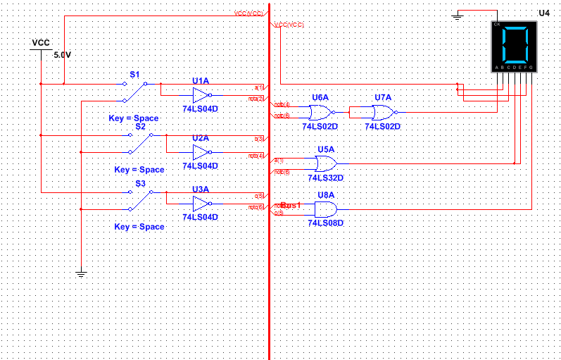
The circuit is in bus form. I used a total of 2 NOR gates, 1 AND gate and 1 NOR gate. Knowing this, I would need 1 NOR chip, 1 AND chip, 1 OR chip and 1 invertor. In this project, we were required to use one NAND or NOR gate in the circuit. I used a NOR gate in my circuit because it used less gates than the NAND gates (nor gate would require 2 gates and nand would require 3 gates) and I needed to add instead of multiply anyways. We use NAND or NOR gates because it may be a more efficient method of constructing a circuit. This is important because it can allow an engineer to create a circuit more efficiently in terms of time and money.
The Seven Segment Display works through logic expressions. Each segment of the seven segment display has its own logic expression . So depending on what number/letter you want to display, you should make the logic expressions accordingly. The main difference between common cathode and common anode is that common cathode must be connected to ground and the segment must be connected to power. With a common anode it would be the complete opposite, it has to be connected to power and then the segment must to be connected to ground. So a common cathode would be on when the segment is one, and be off when it is a zero. With common anode it is the opposite. We used common cathode because it would be easier to view one as on and zero as off, unlike common anode. The purpose of the resistor is to control the amount of current that flows into the Seven Segment Display.
The Seven Segment Display works through logic expressions. Each segment of the seven segment display has its own logic expression . So depending on what number/letter you want to display, you should make the logic expressions accordingly. The main difference between common cathode and common anode is that common cathode must be connected to ground and the segment must be connected to power. With a common anode it would be the complete opposite, it has to be connected to power and then the segment must to be connected to ground. So a common cathode would be on when the segment is one, and be off when it is a zero. With common anode it is the opposite. We used common cathode because it would be easier to view one as on and zero as off, unlike common anode. The purpose of the resistor is to control the amount of current that flows into the Seven Segment Display.
Bill of materials
|
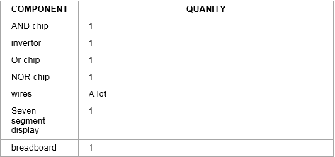
This is my bill of materials. I needed one AND chip, 1 invertor, 1 OR chip, 1 NOR chip, a lot of wires, 1 seven segment display and one breadboard.
|
Bread-boarding

|

|

These 3 images show my breadboard. My second breadboarding experience was much better than my first experience, the reason was because I did not have to do any troubleshooting, it worked the first time, unlike the first time where I had to do a lot of troubleshooting. The only issue I ran into was that I didn't ground my digit 0 before, but I realized this issue when the board didn't turn on when I first checked it. Some skills I learned was color coding my wires, at first I did not color code them since I only had yellow wires when I first worked on it. But later on I went back and color coded the wires and it made it a lot easier to see what wires connect to what and it would have made it easier if I had to go back and troubleshoot.
Conclusion
This project taught me about NOR and AND gates and their functions, and how they can reduce the amount of chips needed. It also taught me more about common anode and common cathode descriptions as well as seven segment displays. It also taught me more about bread boarding. One thing I would do differently with bread boarding next time is color coding my wires from the start so I can better understand where the wires are going and so that I don't have to go back and do it later. K-mapping was useful because it allows me to get the simplified expression in one step. I also understand k-mapping better than Boolean algebra anyways.
