Beginning
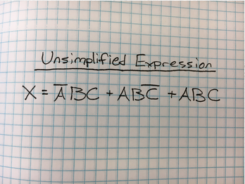
For this project, we were required to create a logic circuit that will detect a paper jam in a copier. The logic circuit had to monitor the copiers 3 inputs (A,B,C), as well as a buzzer and an LED and be able to detect a paper jam. Once the paper jam was detected and fixed, the led would be required to turn off.


Circuits
Why Resistors?
The purpose of the resistors is so that the circuit doesn't get shorted out by too much voltage.
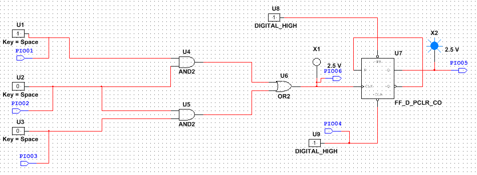
What is the purpose of combinational logic circuit?
The purpose of the combinational logic circuit is too make sure that the LED and the buzzer go off when they're supposed to. In other words it makes sure that the circuit outputs a one when the photo transistors are blocked by paper.
Why do we have a flip-flop?
The flip-flop is implemented so that when the signal from the combinational logic circuit goes to the clock, it toggles. Also, it is there to make sure that when the output is a one, it wont turn off until the clear activates.
Why LED goes off, but buzzer stays on?
Because whenever the logic outputs a 1, the light will be on and when the logic outputs a 0, the light is off. This differs from the buzzer, the buzzer will stay on until cleared.
The purpose of the resistors is so that the circuit doesn't get shorted out by too much voltage.
What is the purpose of combinational logic circuit?
The purpose of the combinational logic circuit is too make sure that the LED and the buzzer go off when they're supposed to. In other words it makes sure that the circuit outputs a one when the photo transistors are blocked by paper.
Why do we have a flip-flop?
The flip-flop is implemented so that when the signal from the combinational logic circuit goes to the clock, it toggles. Also, it is there to make sure that when the output is a one, it wont turn off until the clear activates.
Why LED goes off, but buzzer stays on?
Because whenever the logic outputs a 1, the light will be on and when the logic outputs a 0, the light is off. This differs from the buzzer, the buzzer will stay on until cleared.
Conclusion
The main difference between this project and last project is that the last project used switches as inputs and led's as outputs. This project used motors and input sensors that we haven't used before.
For this project i didn't learn how to wire this because we weren't required to build it, however i did learn how to setup and prepare to build for it as well as how to build it on PLD.
For this project i didn't learn how to wire this because we weren't required to build it, however i did learn how to setup and prepare to build for it as well as how to build it on PLD.
