
|
For this project I was assigned to design a sixty second timer. The timer is supposed to count from 0-59 and then when it reaches 60 it was supposed to reset to 0 and start counting up again. It was also supposed to have a switch that could reset the timer to 0 at any time.
|
PLD Circuit
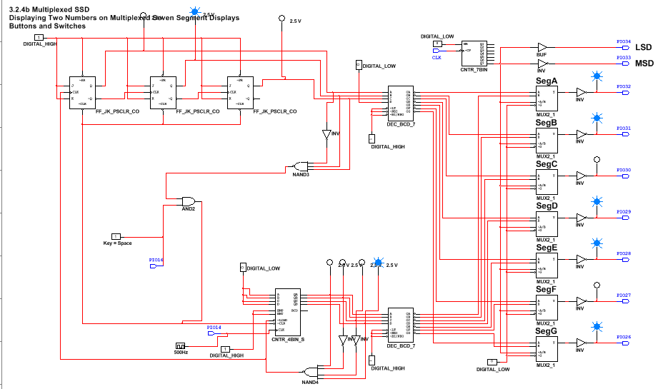
These projects are similar because they both Medium Scale Integration for the 1's unit display and Small Scale Integration for the 10's unit display. They also were both required to have a switch that could reset the number back to zero at any time. These projects are different because the last one used an asynchronous counter that had to pause on 80. For this project, we used a synchronous counter and instead of pausing at the last number, it reset to 0.
Conclusion
The main difference between synchronous counters and asynchronous counters is that synchronous counters are faster and they are connected directly to the clock, which means they have no ripple effect. Asynchronous counters have the ripple effect and they move a bit slower, but they are easier to make and they require less logic than the synchronous counters. The main difference between between 74LS163 and 74LS193 is that 163 is good to use for up counters because you can control where it starts and you can make it stop at the number detected. 193 is alright for an up counter and good for a down counter, the only problem is that its harder to make it with an up counter.
For this project, I made the circuit for the ones display and then created the circuit for the tens display and then later linked them together. I made the ones display so that when it detected a 9, it would turn the 10's display to a 1 and then keep increasing it by one every time it detected a nine. The 10's unit display was an asynchronous counter that counted up to 5 and when it detected a 6 it reset to zero and then continued to count upward every time it detected a 9 in the ones display. I also connected a switch that could reset the whole circuit to 0. When creating this circuit I downloaded the link from the website and then just went off my last project and made corrections to the circuit to have it perform the function that we were assigned. First, i switched the 193's to 163's, and then deleted one of them since only 3 were required for this project, I then rearranged the invertors and gates, switched a couple of them, and added new ones until it performed the function assigned, which was a sixty second timer.
Most of my classmates created the circuits using the same steps, however since there are multiple ways of building this circuit some could have been created differently.
